Magnecraft Relay Wiring Diagram
Http Www Mouser Com Ds 2 357 8501ct1001 271901 Pdf

Schneider Electric Magnecraft 700 Series General Purpose Relay

Magnecraft 781xaxml 24a Power Relay Spdt 24 Vac Coil 15a Contact
Http Www Mouser Com Ds 2 357 8501ct1105 219541 Pdf
Https Stevenengineering Com Tech Support Pdfs 45magnecraft Pcb Reed Relays Pdf

Relays Magnecraft Relay 120 Vac 50 60 Hz W199ax 9 General Purpose

They are represented by the dotted lines in the wiring diagrams.
Magnecraft relay wiring diagram. Every time delay relay has an internal relay usually mechanical with contacts that open close to control the load. Wiring diagram bottom view general specifications ul 508 section 1 magnecraft solution guide 105a ul recognized file no. Magnecraft time delay and sensor relays are designed to provide cost effective solutions for your industrial timing and sensing needs. Available in a wide array of forms fits and functions magnecraft timers offer the ultimate in.
As the industry leader in the electronic relay market. The relay group at schneider electric supports relay requirements with a fast paced program of new product development. Magnecraft is now se relays magnecraft a product range of schneider electric usa includes industrial relays sockets and accessories. Magnecraft a range of schneider electric is a broad line of electro mechanical hybrid solid state relays and sockets used in general purpose and industrial applications.
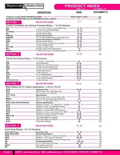
Rated output current contact configuration input voltage vdc coil resistance ω wiring diagram standard part number 0 35 a ac. 0 25 a dc spst no 5 500 a 117sip 1 12 1000 a 117sip 3 spst nc 5 500 b 117sip. Series overview magnecraft general purpose relays series features terminals contact configuration output current page 792 control plug in relay blade dpdt and 4pdt 3 12 a 4 781 plug in relay blade spdt 15 a 9 plug in. E209950 ul c us ul listed when used with magnecraft sockets.
Miniature Pc Board Relays

Magnecraft Relay Schneider Relay Global Magnecraft Distributor
Http Www Mouser Com Catalog Catalogusd 645 1950 Pdf
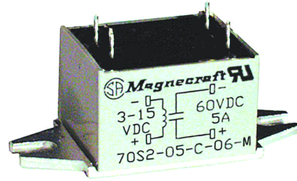
70s2 01 A 05 N Schneider Electric Legacy Relay Solid State Relay

How To Wire Contactor Block With Images Diy Electrical

6225axxszs Dc3 Schneider Electric Legacy Relay Solid State

70 Bsmd 250 Schneider Electric Relays Mouser

70 782xxxx 1 Modules Datasheet Pdf Socket Modules Equivalent

Magnecraft W211cpsrx 1 Time Delay Relay

Schneider Electric Legacy Relays 788xaxc1 120a Relay E Mech

Cm 1370 No And Nc Contacts Of Relay Download Diagram
Ftp Ftp Idec Com Outgoing Marcom Newark Old Newark 2015 All Review Pdf

861ssr208 Dd Schneider Electric Relays Mouser
