Space Shuttle Engine Diagram

Rocket Engine Diagram Google Search With Images Engineering

Space Shuttle Main Engine With Images Space Shuttle Space
Space Shuttle Main Engine With Images Hydrogen Fuel Diagram

Space Shuttle Main Engine Diagram The Main Focus Of Narts Was

Detailed Diagram Of The Raptor Engine Er26 Gimbal Spacex In

All The Pieces Of The Us Space Shuttle Image Tarzan1971 Tumblr

Space shuttle orbiter from space shuttle news reference nasa p 1 8 space shuttle orbiter from space shuttle news reference nasa p 3 4 orbiter structures from space shuttle news reference.
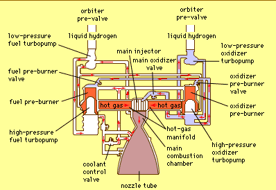
Space shuttle engine diagram. Tx 116 page 248 part iii. Three mounted in the base of the american space shuttle. The rs 25 used in a cluster of three flew in 46 refurbished engine units. Three mounted in the base of the american space shuttle.
Only high pressure closed cycle reusable cryogenic rocket engine ever flown. Space shuttle main engines. Even though a space shuttle main engine weighs one seventh as much as a locomotive engine its high pressure fuel pump alone. Crew module layout figure 3 5.
These made a total of 405 engine flights with no catastrophic in flight failures. Forward fuselage crew module and structure from. The rs 25 engine consists of various pumps valves and other components which work in concert to produce thrust fuel liquid hydrogen and oxidizer liquid oxygen from the space shuttle s external tank entered the orbiter at the umbilical disconnect valves and from there flowed through the orbiter s main propulsion system mps feed lines. Flight deck crew cabin arrangement figure 3 6.
Space transportation system haer no. The space shuttle main engine is a staged combustion cycle engine that burns a mixture of gaseous hydrogen and liquid oxygen. Learn about the chemical reaction that occurs when liquid hydrogen and liquid oxygen are combined to operate the space shuttles three main engines. See how this controlled explosion moves the.
The space shuttle solid rocket booster used in pairs caused one notable catastrophic failure in 270 engine flights. The identifying feature of a staged combustion engine is that most of the fuel flow except for a. Space shuttle main engine introduction the space shuttle main engine ssme was the first and only fully reusable high performance liquid. Whereas in the space launch system sls fuel and.

Rocket Propulsion Space Engineering Vector Illustration Diagram

Technical Drawings

Figure 44 Drawing Of Major Space Shuttle Main Engine
V 2 Rocket Diagram With Images Space Travel Rocket Motor

Technical Drawings With Images Technical Drawing Spacecraft

Image Result For Rocket Engine Diagram Rocket Engine Space

A4 V2 Rocket Engine Diagram Rocket Engine Rocket Rocket Power

Swengines Here Some Ideas About Engine Diagram With Images

Pin De Walter Rigoberto En Pinterest Com En 2020 Naves

Thiokol Atk Space Shuttle Solid Rocket Motor Srm Sts 1 Sts 7

Turbine Stator Blade Cooling And Aircraft Engines Jet Engine

Space Drawing Set 22 V 2 Rocket Engine Diagrams The Unwanted

Engine Turbofan Diagram Indonesia Di 2020
